Witam wszystkich miłośników M110

Późnym latem 2012r odebrałem swoje W126 od mechanika który miał za zadanie poskładać rozebrany wcześniej przeze mnie silnik i wpakować go do auta. Mechanik ten ostatnio nie grzeszy przykładnością i niestety nie wszystko zrobił tak jak należy.
Auto jeździ, ale niestety nie tak jak powinno... Przejechałem nim ok 2000km, ale auto chodzi bardzo topornie:
- Na jałowym biegu wypadają zapłony
- Przy próbie ruszenia z miejsca silnik się strasznie dławi
- Za autem czuć nieprawidłowy skład mieszanki
- Silnik z trudem wkręca się na wyższe obroty, dopiero przy ok 3000 obr/min występuje lekka poprawa.
- Silnik dławi się nie tylko podczas ruszania, ale także przy próbie przyspieszania.
- Mam wrażenie że przy dodaniu gazu słychać strzały z wydechu...
Jestem w 100% pewien że silnik ma obecnie ustawiony zbyt duże luzy zaworowe (na zimnym silniku ustawił 0,15/0,30). Wiem też że zapłon nie jest ustawiony jak należy (ustawiał na szybko, nie wiem dokładnie jaki kąt ustawił, ale jeździłem na poprawkę).
Dzisiaj znalazłem wreszcie troszkę wolnego czasu i postanowiłem sprawdzić co tam się dzieje...
Na początek zmieniłem kopułkę i palec (kopułka która była zamontowana pochodziła ze strychowych zapasów więc wolałem ją zmienić) oraz sprawdziłem podciśnienia. Wychodzi na to rozdzielacz zapłonu jest prawidłowo połączony z górnym króćcem podciśnienia przy przepustnicy. Dolny króciec który normalnie idzie do termozaworu sterującego EGRem jest zaślepiony (dlatego że przy demontażu silnika urwał się króciec przy tymże termozaworze). Pozostałe podciśnienia niestety nie są podłączone.
Posiłkując się opracowaniem znalezionym w internecie:
http://forum.mercedes-benz-clubs.com/vi ... fa2#p77103Cytuj:
I was finally able to borrow a shop manual for the M110, from Peter Coseip. Thanks, Peter!
For the benefit of gearheads who may one day find this in a Google search, I am posting an explanation of the vacuum connections for the engine, which has long been a source of darkest mystery to many M110 DIY'ers.
I will try to do this without a single diagram(!)
Unfortunately, this post does not cover the carburettor engines.
There are four vacuum sources, all small pipes, on the M110 K-Jetronic injected engines. Let's call them 1. to 4.
1. and 2. are two small pipes coming out of the throttle valve, at the front of the intake manifold at the left side of the engine. One is right on top of the other. The TOP one goes to the distributor vacuum advance, the BOTTOM to the EGR valve on the top of the exhaust manifold on the other side of the engine. The EGR valve looks like a flying saucer and has a steel pipe coming out of it that leads under the front of the engine and up again into the intake manifold.
1. and 2. are very often switched because they seem identical, but apparently, they are not, I think one cuts off earlier than the other. They both have low or no vacuum at idle. Vacuum increases with rpm, while the other sources, 3. and 4., have the opposite, vacuum decreases with rpm. Increasing vacuum with rpm advances the spark timing and opens the EGR (Exhaust Gas Recirculation) valve more.
3. is on the inlet manifold at the left side of the engine, roughly under the middle runners, it is a single small source pipe pointing away from the engine. 3) should have a single rubber hose connecting it to a short length of plastic hose, which then plugs into a black rubber 4-way hose connector. Obviously, you could plug the 4-way straight into the source pipe, but I think the reasoning behind the extra connection is to spare it from the heat of the engine, so it lasts longer. The three remaining branches of the 4-way are connected as follows:
3a) goes to the top-pointing vacuum "input" of an electrical vacuum switch, which on the W126 is located on the front left fender directly behind the left headlamp. There may be two of these, see 3b). The switches can be alloy and cylindrical (W116, W123) or look like a black plastic box relay. They should have an electrical connection. The side "output" of switch 3a) leads to the vacuum input of the deceleration air valve 1, a round black plastic object located under the air cleaner housing and outside the middle of the intake manifold along the left of the engine. It should be visible even without removing the air cleaner. It plugs into the bottom of the air cleaner and connects to a rubber hose that leads eventually into the lower intake manifold.
The principle of this system is that when you take your foot off the pedal at speed, high vacuum in the lower intake manifold opens the air valve, allowing air from the air cleaner directly into the lower intake manifold, bypassing the upper intake manifold's fuel sensor plate and throttle. The resulting absence of vacuum in the upper intake manifold makes the fuel sensor plate return to its idle position, cutting off most of the fuel. The unthrottled rush of air into the cylinders also decreases pumping losses. The electrical switch is to ensure the valve only opens during deceleration/overrun, not at idle. If you connect the air valve directly to high manifold vacuum at idle, the engine should die. If it doesn't, the air valve may not be working or some adjustment may be off, or there may be a vacuum leak. You can live without this system, but your fuel consumption will be higher by 20% or more.
3b) goes to the top input of another electrical vacuum switch, this one for the air conditioning idle-up valve. This switch generally is identical to 3a), and in the W126 is installed alongside 3a), but farther away from the left headlamp. The way to test if the switch is 3b) and not 3a) is simply to turn on the airconditioning and unplug the side vacuum output. If the switch is 3b), there should be vacuum at the side output during idle with aircon. If it is 3a), there will be no vacuum. The side output of 3b) leads to the aircon idle-up valve, a cylindrical black plastic object connected to black rubber air hoses, located alongside the lower left of the engine block, under the idle adjuster mechanism, beneath the distributor. It's impossible to see from above, you should put the car on a lift and look from below.
The principle is that when you turn on the aircon, the vacuum opens the aircon idle-up valve, allowing a little additional air into the intake manifold, which raises the idle speed a couple hundred revs to compensate for the aircon load. You can live without this system, but you will have to raise the base idle speed or the engine may die when you switch on the air conditioning. Higher idle may in turn affect fuel economy.
3c) goes to an additional air valve 2, a thick alloy disk located on the bottom left side of the engine block underneath the distributor near the sump, and connected by black rubber hoses to the same network as the aircon idle-up valve described above and thence to the intake manifold. Mercedes calls this valve the "schubumluftventil", which various internet dictionaries render as "thrust air valve". Do not confuse this valve with the nearby cold start air valve, which is also alloy, but is more cylindrical, has no vacuum connection, and is bolted to the engine block. Air valve 3c) seems to fulfill a similar function as air valve 3a); why there are two, I have no idea— but I'm sure there's a reason. My theory is that 3c) is for acceleration, and 3a) for deceleration. By the way, 3c) does not have an electrical connection, and it has a small rubber plug in the center.
For cars with TWO vacuum connections to the diaphragm on the distributor (one for advance, the other for retard), connect 3c) to a Y-connector and take branch 3c1) to the air valve and branch 3c2) to the distributor vacuum retard. Generally, the connection pipe for advance is on the "outside" of the diaphragm housing in relation to the distributor, while the connection for retard is on the "inside". Let me be the first to say that having a system where you can mess up the connections so easily, IS retarded. For US versions, there may be an electrical vacuum switch between the source and 3c2).
4. on the earlier models, is a vacuum source pipe, pointing upwards, on the top surface of the rearmost runner of the intake manifold, closest to the firewall. This should have a short hose like the 4-way, then go into a 2-way or "Y" connector, to create 4a) and 4b). In the later models, 4a) and 4b) are two separate pipes near each other. 4a) is fatter than 4b). The two branches go to:
4a) goes to the warm-up compensator, an alloy box bolted onto the rear left side of the engine block deep underneath the intake manifold near the firewall. The warm-up compensator has two steel fuel lines connected to it. It's hard to see it from above, best to put the car on a lift and see it from below.
The vacuum system on the warm-up compensator is for load enrichment. The principle is, when you floor the throttle, the vacuum to the warm-up compensator dies out, opening a valve that delivers a surge of fuel to the injectors. When this isn't working, you will get a rattling or "pinking" pre-ignition noise ("tope") when you floor the throttle, even if your ignition advance and mixture are set properly. In essence, this system allows your engine to idle quite lean (compared to a carb) and thus improves fuel economy. It also gives it more immediate throttle response.
The early warm-up compensators (W116, W123) have a single vacuum connector on the "front" (the side opposite the engine block). Later ones have two connectors, one on the front and one on the side. In the intermediate series (before Sept 81), the vacuum should be connected to the front. The side pipe is a vent, and should be connected to a small nipple in the hose underneath the idle air adjuster all the way at the front left of the engine, (so dirt won't get into it). In the Sept 81 and later series, the connections are reversed: the side one is the vacuum, and the front one is the vent. There is a way to test which is the right connection. Run the engine warm. Disconnect the vacuum hose to the warm-up compensator, and the idle should go up slightly. I've never tried this, though.
4b) goes to the vacuum central locking and other stuff in the car body, including the vacuum "economy" gauge. The connection comes out of the left side of the firewall (alongside the relay and fuse box on the LHD W126), and generally has a cylindrical check valve. In the W126, it also has Y connectors, for the locks and the vacuum gauge.
5. There is one final connection which, strictly speaking, is not a vacuum connection; it's a vent. This is at the rear of the fuel pressure damper (could be the accumulator, I get them mixed up), a small alloy cylinder a bit larger than a film canister that is generally found bolted to the top inside part of the intake manifold (you generally have to remove the air cleaner housing to find it) and has steel fuel lines coming out of one end. On the end opposite the fuel lines is a small pipe that looks exactly like a vacuum connection, and uses the same hoses. This is meant to be connected to slight vacuum at any of:
5a) the flat rubber vent hose connecting the camshaft cover to the top of the air cleaner (the hose should have a nipple for this purpose);
5b) the air cleaner itself, which would have a connection, generally on the bottom;
5c) on the G-wagen and some others, to the nipple on the hose between the aircon idle-up air valve and the idle speed adjuster-- the same one the warm-up compensator vent plugs into, so if this is the only alternative, you will need a Y connector.
The only reason Mercedes put a hose on this thing is so fuel vapors won't vent to the hot air around the engine and cause a fire. It doesn't affect engine performance, just a safety issue, and not even a grave one.
To summarize, here's the list:
1. From throttle to distributor vacuum advance
2. From throttle to EGR valve
3. From center bottom of intake manifold to 4-way connector, to:
3a) Deceleration/overrun air valve 1 via electrical vacuum switch
3b) Air conditioning idle-up air valve via electrical vacuum switch
3c) Acceleration air valve 2 (schubumluftventil)
3c2) (optional) Distributor vacuum retard
4. From rear top of intake manifold to:
4a) Warm-up mxture compensator
4b) Vacuum central locking and other body mechanisms
5. Vent connection from fuel pressure damper
Good luck! If you are local (Manila) and need help on this, just PM me.
Opracowałem własną skróconą wersję w ojczystym języku:
Cytuj:
1 - górny króciec przy przepustnicy - idzie do rozdzielacza zapłonu - odpowiada za przyspieszenie kąta zapłonu (gdy rośnie podciśnienie)
2 - dolny króciec przy przepustnicy - idzie do EGRa - odpowiada za otwieranie EGRa (gdy rośnie podciśnienie)
3 - wychodzi z kolektora, rozdziela się na 4 wyjścia:
3a wychodzi do przełącznika na lewym błotniku za lampą (mogą być dwa takie) jedno wyjście z przełącznika idzie do zaworu pod filtrem powietrza - pozwala na szybkie odcięcie paliwa przy nagłym zamknięciu przepustnicy, elekryczny przełącznik sprawia że zawór jest otwarty tylko przy hamowaniu silnikiem a nie na biegu jałowym
3b do klimy - nie powinno go być u mnie
3c idzie do zaworu powietrza dodatkowego pod rozdzielaczem, nie ma on połączeń elektrycznych a jedynie gumową wtyczkę na środku
4 - kolektor ssący z tyłu silnika (4a jest grubsze od 4b)
4a idzie do warmup compensatora pod kolektorem ssącym - zanik podciśnienia powoduje wzbogadzenie mieszanki
4b zasila podzespoły typu ekonomizer, centralny zamek, itp.
Stan tychże przedstawia się następująco:
1 - zdaje się być podłączone prawidłowo
2 - tak jak już napisałem nie mam gdzie go podłączyć - kojarzy ktoś może czy brak tego podciśnienia powoduje może otwarcie EGRa? Kiedy dokładnie powinien otwierać się zawór spalin EGR?
3 - nie znalazłem tego króćca w kolektorze - ma ktoś z Was jakiś schemat lub da mi wskazówki gdzie go szukać?
3a - przełącznik z tyłu lewej lampy nie jest podłączony do kolektora, ale jest za to podłączony do zaworu pod filtrem powietrza
3b - nie mam klimy, więc nie mam tego podciśnienia
3c - nie znalazłem, chyba nie bardzo wiem czego szukać
4 - znalazłem, u mnie jest to wersja z dwoma osobnymi króćcami (cieńszy podaje podciśnienie do ekonomizera, itp)
4a - nie udało mi się bez latarki wymacać czy jest dobrze podłączony
4b - jest podłączony prawidłowo
Koledzy pomóżcie ogarnąć ten chaos i cieszyć się zdrowym M110

EDIT:
Chyba znalazłem właściwy diagram:

Znalazłem też fotkę zaworu nr 96:

Jest też schemat z EPC na którym coś tam widać:
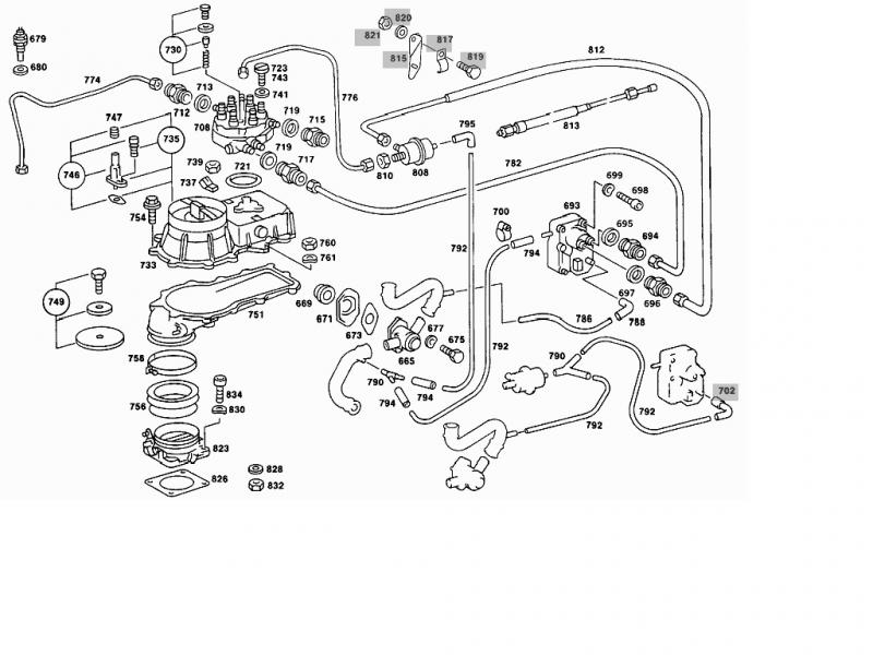
Super fotka obrazująca położenie i połączenia zaworu 96:

Zapomniałem też wspomnieć że jeden z poprzednich właścicieli (Niemiec) zamontował katalizator, sondę oraz urządzenie sterujące które prawdopodobnie zmienia ciśnienie paliwa za pomocą elektromagnetycznego wtryskiwacza zlokalizowanego obok rozdzielacza paliwa K-Jetronic. Dodam też że przed remontem silnika wszystko działało jak należy, więc raczej nie podejrzewam usterki tego układu.